That's a really clean build! I think AES has the white Cliff jacks.
Jack
Moderators: zaphod_phil, Daviedawg, Graydon, CurtissRobin, colossal

That's a really clean build! I think AES has the white Cliff jacks.

1/4" Jack - Cliff, White, Solder Lug


It sounds like you have an oscillation problem. You can try chopsticking the wires to get rid of the effect, or use shielded wire and see if that helps. Post some photos of the FX loop and surrounding area.Billy_Goat wrote: ↑Tue 03/02/21 6:52 pmAfter a fair bit of playing and fussing with effects in the FX loop, it appears that the FX loop on my build is exhibiting a bit of comb filtering and / or phasing shifting that is manifesting as a slight unpleasant ‘hollow’ sound overall compared to when I play without using the FX loop. Not sure how to further confirm this and / or how I would go about trying to rectify if in fact more than just my impression? Any thoughts?
JMPGuitars wrote: ↑Tue 03/02/21 7:18 pmIt sounds like you have an oscillation problem. You can try chop-sticking the wires to get rid of the effect, or use shielded wire and see if that helps. Post some photos of the FX loop and surrounding area.Billy_Goat wrote: ↑Tue 03/02/21 6:52 pmAfter a fair bit of playing and fussing with effects in the FX loop, it appears that the FX loop on my build is exhibiting a bit of comb filtering and / or phasing shifting that is manifesting as a slight unpleasant ‘hollow’ sound overall compared to when I play without using the FX loop. Not sure how to further confirm this and / or how I would go about trying to rectify if in fact more than just my impression? Any thoughts?
Thanks,
Josh
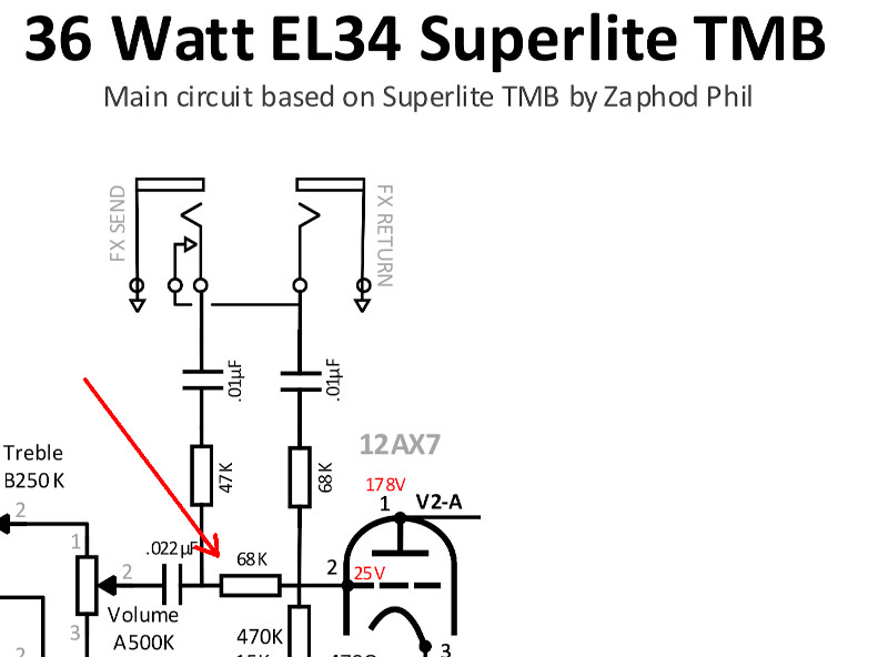
TriodeLuvr wrote: ↑Thu 03/04/21 10:11 pmIs it wired like this? What's to keep the loop return signal from mixing (potentially out of phase) with the dry signal from the 68K resistor?
Hi TriodeLuvr,
Yes, 68K resistor was in place as required. Thanks!
Hey Josh,JMPGuitars wrote: ↑Fri 03/05/21 10:05 amYour tag board appears to me that it is essentially allowing your loop circuit to run parallel to long plate wires running next to it.
Take a look how I implement the FX loop: viewtopic.php?p=247480#p247480
I keep all parts (except the 68K which I place directly on the circuit board) running in simple lines, which helps avoid issues like parallel plate wires that you currently have. It may not be the source of the problem, but from the photo, it appears to be the most likely cause.
Changing to the method I use will eliminate that issue and help you see if it's the cause. I don't use any extra wires, the leads from the components are all I you really need. I leave just enough slack to chopstick if needed.
Thanks,
Josh
No worries, I understand that not everybody likes to do things PTP, and I too prefer mechanical support for things. BUT, consider this: if you make good mechanical connections on the solder joints, and twist the leads of the components before soldering, you still have mechanical connections and support. The FX loop is physically light, and shouldn't generate any heat, so risk is low. Another option is to use your tag board to hold a zip tie locking the loop physically in place. There's plenty of ways to deal with it, find what works best for you. That's assuming you haven't already sorted the problem.Billy_Goat wrote: ↑Mon 03/08/21 2:54 pmWith all due respect, I'm not a fan of wiring components without providing solid mechanical attachment for the same which your photo appears to indicate, so I built a little turret board where the two caps connect directly to the jacks and the two 'in series' resistors from the caps are attached to turrets. Then shielded wire from there to the main turret board and the last 68K resistor placed on the main turret board. I also added some foil shielding underneath the FX turret board and grounded that. The new turret is also now 1.5 inches above the plate wires lying on the chassis. All components and wiring is now more or less 90 degrees away from the plate wiring lying against the chassis. Nothing parallel.
It seems better upon first check, but admittedly I only had a few mins to play and analyze. So, the jury is still out atm.
If it's determine that this rebuild is still not working properly, I'll reluctantly try wiring as your photos suggests.
Cheers
My point was that the 68K might allow a return signal to mix out-of-phase with the dry signal and create the comb effect you're describing.Billy_Goat wrote: ↑Mon 03/08/21 2:54 pmHi TriodeLuvr,TriodeLuvr wrote: ↑Thu 03/04/21 10:11 pmIs it wired like this? What's to keep the loop return signal from mixing (potentially out of phase) with the dry signal from the 68K resistor?
Yes, 68K resistor was in place as required. Thanks!
Hi Jack,TriodeLuvr wrote: ↑Mon 03/08/21 3:33 pmMy point was that the 68K might allow a return signal to mix out-of-phase with the dry signal and create the comb effect you're describing.Billy_Goat wrote: ↑Mon 03/08/21 2:54 pmHi TriodeLuvr,TriodeLuvr wrote: ↑Thu 03/04/21 10:11 pmIs it wired like this? What's to keep the loop return signal from mixing (potentially out of phase) with the dry signal from the 68K resistor?
Yes, 68K resistor was in place as required. Thanks!
Jack
You might want to disconnect one end of the 68K and try it again, just as a test. That would eliminate the possibility of an out-of-phase mix from your effects device.Billy_Goat wrote: ↑Mon 03/15/21 8:45 amHi Jack,TriodeLuvr wrote: ↑Mon 03/08/21 3:33 pmMy point was that the 68K might allow a return signal to mix out-of-phase with the dry signal and create the comb effect you're describing.Billy_Goat wrote: ↑Mon 03/08/21 2:54 pm
Hi TriodeLuvr,
Yes, 68K resistor was in place as required. Thanks!
Jack
Sorry, I thought you were asking if I had installed the 68K resistor rather than asking if the 68K resistor might be causing a mixing issue.
With the above in mind, I don't know, but I'm guessing that could be in play based on how I believe the circuit is likely working. Either way, I followed the build as documented. Are you suggesting removing or altering something here?
Cheers
Assuming it's wired correctly, this method has been around for a long time, and is well tested. The only issues I've seen are PO if it's placed poorly, or the fact that it's passive doesn't work for all effects.TriodeLuvr wrote: ↑Mon 03/08/21 3:33 pmMy point was that the 68K might allow a return signal to mix out-of-phase with the dry signal and create the comb effect you're describing.
Jack
Josh,JMPGuitars wrote: ↑Mon 03/15/21 1:52 pmAssuming it's wired correctly, this method has been around for a long time, and is well tested. The only issues I've seen are PO if it's placed poorly, or the fact that it's passive doesn't work for all effects.TriodeLuvr wrote: ↑Mon 03/08/21 3:33 pmMy point was that the 68K might allow a return signal to mix out-of-phase with the dry signal and create the comb effect you're describing.
Jack
They are cliff jacks, and they're wired the same as my diagram. I don't know that all Cliff jacks are exactly the same (but most probably are). Though I suspect yours are wired the same as mine anyway, but you switched the jumper wire to the outside instead of inside. It shouldn't matter since one side of the jumper should be lifted when both jacks are inserted.Billy_Goat wrote: ↑Mon 03/15/21 3:36 pmJosh,
I'm wondering if I still have incorrect wiring on the jacks?
The image you pointed to for your build example isn't high enough res for me to zoom in closely to clearly analyze, but are you using CLIFF jacks for your FX jacks? If so, it would appear the BLUE the wire I have connecting my two FX jacks are NOT connected as you have your jacks connected together? Assuming your jacks are CLIFF and all CLIFF jacks are mechanically the same, am I mis-reading this?
Cheers
Jack,TriodeLuvr wrote: ↑Tue 03/16/21 11:22 amDoes the loop exhibit this issue if you plug in a patch cable?
Jack