Daviedawg wrote: ↑Tue 01/12/21 3:23 am
Sadly I am no help on the combo front. But I built a stand alone reverb based loosely on the Fender VTR63. The transformer is fed from the pentode of a 6U8 and picked up by a triode in a 12AT7. The 6U8 is running at the same voltages as it does in my amp circuits.
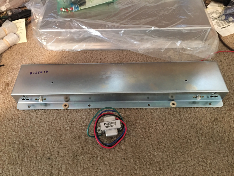
The transformer is a low wattage audio transformer which is the same as the choke in the circuit. My tank is a 9AB3C1B like yours I think.
It has run many hours in virtually constant use for more than six years so that combination is proven to be robust.
Dd
Thanks for mentioning the 6U8. It's a nice tube, and I've used it in other applications in the past.
I finally found a reference to all this last night, a Fender schematic that shows AC signal levels throughout the amplifier. The numbers are highly dependent on frequency, but it’s a guide. I also simulated the Fender circuit to verify the gain in each section and to confirm maximum available levels.
It turns out that the amplitude driving the 24K:8 ohm transformer is higher than a single section of a 12AT7 can produce. It simply doesn’t have sufficient current capability (clearly the reason they used two sections in parallel). A single section of a 12AU7 could provide the current, but it lacks sufficient gain. On the recovery side, Fender used a 12AX7, so neither the 12AU7 or 12AT7 have enough gain to replicate Fender’s signal voltages.
I also modeled the Marshall front end from the Low input through to the tone stack. At the circuit locations where it’s most practical to pick off and inject the reverb signal, more gain is needed to duplicate Fender’s numbers than can be accomplished with a 12AT7. The bottom line is that Fender’s reverb functionality can’t be cloned into the Marshall with a single bottle in the reverb “module.”
After futzing with the simulator for many hours, I’ve decided to take a two-pronged approach. First, I’ll build this to use a single 12AT7 around the reverb tank. That won’t duplicate Fender’s drive amplitude or recovery gain, but it might still be useable. Some builders have reported satisfactory results with this configuration in other amplifiers. If it turns out not to have full effect, I'll go to plan B. First, the 12AT7 will be changed to a 12AU7. Then, I’ll bias one of the cathodes to +20V or so using a Zener. This voltage will be used to power a dual, low-power opamp. The opamp can easily compensate for the low gain of the 12AU7 in both drive and recovery, effectively matching Fender’s numbers for operation of the tank.
I know this might sound complicated, but the entire opamp circuit can fit on a PCB the size of a postage stamp. Boards like this are currently being sold on the ‘Bay for a couple dollars each, and it's really a straightforward approach to getting this done without re-engineering the entire signal chain. I also won't have to cut more holes after the amp is built, which is one of my primary goals.

Jack