P.S. i cant wait to see some reponses to this:)
The results of heat on PCB mounted tube sockets...
Moderators: zaphod_phil, Daviedawg, Graydon, CurtissRobin, colossal
-
Icetech

- Frequent poster

- Posts: 542
- Joined: Sat 06/18/05 2:00 am
- Location: Macomb, MI
- Contact:
-
dartanion
- Extremely Active Poster!

- Posts: 3100
- Joined: Tue 01/25/05 2:00 am
- Location: RWC, CA
That's actually not a bad looking PCB, albeit the obvious meltdown issue.
Ever looked inside a VCR or TV? EVIL PCB in there!
How much excess expense do you think it really is to have chassis mounted sockets while using a PCB? Can't be that much? I guess it would be hard to have a machine solder those, so the expense is forgone.
Ever looked inside a VCR or TV? EVIL PCB
How much excess expense do you think it really is to have chassis mounted sockets while using a PCB? Can't be that much? I guess it would be hard to have a machine solder those, so the expense is forgone.
0 x
-
jersey_aaron

- Verbose poster
- Posts: 1179
- Joined: Sat 09/27/03 2:00 am
- Contact:
"DISCLAIMER: This is not intended to start a flame war >> It's informational only."
Not when the title of your post is "The results of heat on PCB mounted tube sockets...".
One board in one Soldano amp does not represent EVERY PCB with on-board tube sockets. Its ignorant to even remotely assert that. There are dozens of PCB guitar and hi-fi amps with tubes mounted on the board that have been around since the 1960's that are fine. There are also poorly manufactured guitar and hi-fi PCB amps that have failed miserably.
Posting a picture of a poorly manufactured PCB with a meltdown and shouting "ALL PCB'S ARE BAD!" doesn't prove anything, except that your particular Soldano Astroverb had a poorly manufactured PCB. But at least now we know you're a troll.
0 x
-
KingCrimson

- Old timer, Never stops talking
- Posts: 2272
- Joined: Wed 08/04/04 2:00 am
- Location: Lakeland, Florida, USA
Jersey,
My apologies for not knowing this; I've been very busy - but have any fellow 18-watters bought your board yet and used it?
I'd like to see some reviews.
I actually recommended your board to a friend who is in the market for an amp who has never built an amp. I thought it would be a good way to get initiated into amp building.
And what's the best band to ever come out of Hackensack?
0 x
-
Icetech
- Frequent poster
- Posts: 542
- Joined: Sat 06/18/05 2:00 am
- Location: Macomb, MI
- Contact:
-
stevesuk
- Frequent poster
- Posts: 893
- Joined: Sat 07/19/03 2:00 am
- Location: UK
- Contact:
Hello Dummy calling.
I am building one of JAs PCB boards into one of my home made chassis and using my own manufactured fascia plates.
I have built several dozen amps from scratch including the chassis, boards, mostly with original RS holeboard and turret tags, built the head or combo boxes, upholstered the cabs and also made my own tea. I was also one of the first, if not the first to build the 36 watt TMB (with lots of help from Richie). That amp has been gigged for probably a year ? several times a week and is still going strong.
I am building the PCB because a guy with a studio wants a super quiet amp, My amps are normally quiet, but not silent. No problem in a noisy Pub or club.
I am also building it with an open mind, but some slight modifications through necessity.
The pots are not mounted on the board, because my fascia doesn't quite line up, they will have fly leads.
Same with the input jacks, short fly leads.
Output jacks direct on the PCB, how often is a speaker plugged in and out of a combo ?
I did intend to chassis mount the valve bases, but I thought I would try one with the bases mounted on LONG LEGS directly on the board.
So far no problem, the easiest board I have ever built !!
I haven't used instructions, because if you have built before it is self explanatory.
I found a possible solution to the doom and gloom merchants in my bits box, unfortunately being a Dummy I have forgotten where it came from. It is a sort of extender, which just has pins and a socket in a plastic 'thing'. Anybody seen one before ? or know where to get them ?
I will use this one and monitor the board to see if there is any difference.
I can tell you the 1977 vintage Marshall 100 watt 2103 combo I have just got with a basic PCB board is inferior to JAs board.
Mainly because it is, one sided and not plated through, which means the board has to come out to replace a component properly, unless the heat is transferred down the leg of the component to melt the solder underneath, and who knows what is happening underneath ?


I am using a GDS mains and a drake OT. I am now determined to spend the rest of the day finishing this one, so I can order another and take advantage of the dollar/pound situation.
Steve UK
I am building one of JAs PCB boards into one of my home made chassis and using my own manufactured fascia plates.
I have built several dozen amps from scratch including the chassis, boards, mostly with original RS holeboard and turret tags, built the head or combo boxes, upholstered the cabs and also made my own tea. I was also one of the first, if not the first to build the 36 watt TMB (with lots of help from Richie). That amp has been gigged for probably a year ? several times a week and is still going strong.
I am building the PCB because a guy with a studio wants a super quiet amp, My amps are normally quiet, but not silent. No problem in a noisy Pub or club.
I am also building it with an open mind, but some slight modifications through necessity.
The pots are not mounted on the board, because my fascia doesn't quite line up, they will have fly leads.
Same with the input jacks, short fly leads.
Output jacks direct on the PCB, how often is a speaker plugged in and out of a combo ?
I did intend to chassis mount the valve bases, but I thought I would try one with the bases mounted on LONG LEGS directly on the board.
So far no problem, the easiest board I have ever built !!
I haven't used instructions, because if you have built before it is self explanatory.
I found a possible solution to the doom and gloom merchants in my bits box, unfortunately being a Dummy I have forgotten where it came from. It is a sort of extender, which just has pins and a socket in a plastic 'thing'. Anybody seen one before ? or know where to get them ?
I will use this one and monitor the board to see if there is any difference.
I can tell you the 1977 vintage Marshall 100 watt 2103 combo I have just got with a basic PCB board is inferior to JAs board.
Mainly because it is, one sided and not plated through, which means the board has to come out to replace a component properly, unless the heat is transferred down the leg of the component to melt the solder underneath, and who knows what is happening underneath ?
I am using a GDS mains and a drake OT. I am now determined to spend the rest of the day finishing this one, so I can order another and take advantage of the dollar/pound situation.
Steve UK
0 x
-
allynmey

- Verbose poster
- Posts: 1131
- Joined: Sat 12/04/04 2:00 am
- Location: Dighton, MA USA
- Contact:
Hi all, Steve, where did you get those extenders? I'd like to get a set for my JA PCB Build. I have the PCB board (looks pretty rugged). I do have a concern about the el-84's and heat. This seems like a reasonable solution. Maybe JA should get a supply of them and include 2 of them in the kit for el-84's. I am waiting for a chassis from JA to get started and for the most part, I am happy for the quality of the parts. I've heard JA's PCB TMB in person and it sound good! apparently some final changes have been made and now it sounds better I hear! Maybe this weekend JA will come to Greg's get together and we can get some clips.
I applaud him for trying something, if not new, but different.
Allynmey
I applaud him for trying something, if not new, but different.
Allynmey
0 x
-
rjgtr
- Builder, Admin

- Posts: 6668
- Joined: Wed 11/24/04 2:00 am
- Location: Jax, FL
- Contact:
The fact is all PCB mounted sockets transfer heat to the PCB, long or short legged. Heat will cause issues with more common amps, like Fenders and Marshalls.
Amps that use a better circuit board and layout design, like Riveras, don't have the kind of damage that you can regularly see in others. Rivera does have PCB mounted sockets, but puts the Sockets toward the edge of the PCB so there is space for the hot air to rise to the top of the combo. The PCBs also appear to be military spec and are through plated.
Soldano also knows it can be a problem which is why their high end amps, like the SLO, fly the pots and tube sockets and the board is in between the tube sockets not on top of them.
As for JA's board, only time will tell, but it looks pretty well made to me and he has made some effort to let the heat escape and not get trapped on the bottom of the tube socket. We'll have get someone to open up a JA TMB in 6 months of hard playing to see what the results are, but I'd bet it will look Ok.
0 x
-
novemberrain
- Verbose poster
- Posts: 1191
- Joined: Sat 01/22/05 2:00 am
Those "little extenders" used to be widely available as "socket savers" for tube testers, what you're supposed to do is plug 'em in so your changing tubes in the "socket saver" which, true to its name, then saves your sockets. They also work well for people who have a zillion tubes they swap back and forth in their amp.
AES/CE has 'em at the moment.
Using them to reduce heat transfer to a PC board is a pretty clever application.
AES/CE has 'em at the moment.
Using them to reduce heat transfer to a PC board is a pretty clever application.
0 x
-
csbradley
- Occasional poster

- Posts: 433
- Joined: Wed 10/13/04 2:00 am
- Location: SF Bay area
Why not make some measurements and do some testing. I believe FR4 is rated at 135 degree C, with a UL 94-V0 flamability rating. (Would have to check on this, not 100% sure.) I don't even know if discoloration is a sign of potential failure.
If anyone wants to take me up on this, we have a thermal imaging camara here at work. Get the datasheets from the PCB manufacturer, and we'll run the amp full out for some power testing. We can check the temperatures of the tubes, the board, socket pins, and PCB traces, and see if any of the specs are being exceeded. We can also determine how far the temperature creeps along the traces, and see if there are in component issues, and if needed, determine how far the components should be from the Tube sockets. With enough time (and samples), we could also look over what type of venting on the PCB provides the best heat escape.
I could also look over creepage and clearances for the high voltage traces. Creepage of high voltage from one trace to another is one of the failures I've seen on PCB tube amps.
Power testing, while monitoring heat exchange through the PCB could be done in a day, and shouldn't blow up anything. If anyone is actually interested in doing real testing, let me know. I don't have a PCB amp, but if someone is willing to donate one for a few days and pay shipping, I'll donate the time to do the tests.
Just an offer....
CSB
0 x
-
stevesuk
- Frequent poster
- Posts: 893
- Joined: Sat 07/19/03 2:00 am
- Location: UK
- Contact:
-
nigelb
- Occasional poster
- Posts: 405
- Joined: Thu 08/07/03 2:00 am
- Location: Cardiff, South Wales
- Contact:
Steve, you got it with the valve tester you got off mestevesuk wrote:Novemberrain,
Thats it
I'll try and source some from the valve tester specialists in the UK.
Steve UK
I haven't seen them anywhere in the UK, don't think you'll get them here, they're an 'American' thing. I got a few on e-bay from a guy in Hong Kong (audioguy) but he doesn't seem to do them any more. CE Distribution do them. If you want any, get in touch I am probably placing an order with them in a few days.
Nigel
0 x
-
jersey_aaron
- Verbose poster
- Posts: 1179
- Joined: Sat 09/27/03 2:00 am
- Contact:
Wow  , it looks so different to me with your parts, especially the radial/axial substitutions and the mustard caps. I like the headers on the output board, nice idea.
The socket savers are a good idea, but I don't think they're needed if you use a JA TMB chassis. When the board is mounted, all of the tube sockets will be level with the top of the chassis. Air will be able to circulate around the tubes, and the aluminum chassis will absorb the heat, which will constantly be rising up and AWAY from the PCB underneath.
I can't wait till you fire it up!!!
0 x
-
stevesuk
- Frequent poster
- Posts: 893
- Joined: Sat 07/19/03 2:00 am
- Location: UK
- Contact:
Hey Nigel,
I would like 12 'base extenders' if you can get them, I'll email you.
Aaron,
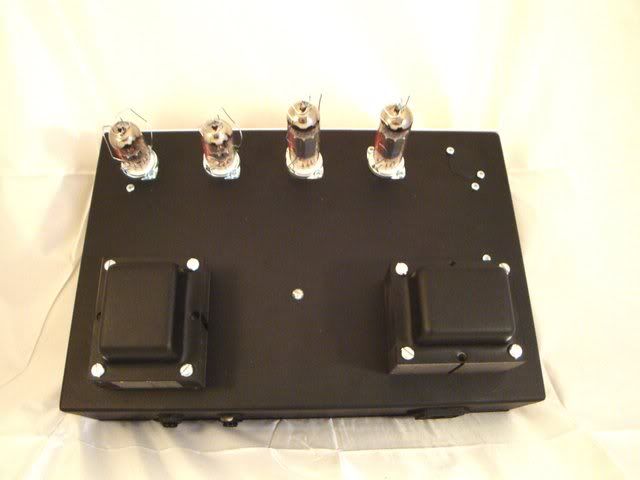
I did intend to bolt the bases to the chassis by using 'studs' fixed to the bases with nuts and then pushing them through holes and putting nuts on from above. In that way I can use shielded tops with cans on the ECC83s and spring retainers on the EL84s.
This one is going in a combo so the valves will be horizontal.
What do you think about the OT being inside with the primary connection less than an inch from the PCB connections? I got the idea from the scrap 20 Watt I got last week.
I am well pleased with the quality of the board and it is a breeze to complete. I also get to use all my 'short legged' parts I didn't throw away. I have just reclaimed 35 mustard cap 0.022uFs and they will sit nicely in one of your PCBs.
I am wondering about all the 'extras' you have allowed for on the board, footswitches etc. Also a chassis template for the valve base holes would be brilliant for people like me who roll there own.
I haven't needed the instructions, but would be nice to read, when are they due on your website?
I hope you still have some boards left for when I have finished this one.
Steve UK
I would like 12 'base extenders' if you can get them, I'll email you.
Aaron,
I did intend to bolt the bases to the chassis by using 'studs' fixed to the bases with nuts and then pushing them through holes and putting nuts on from above. In that way I can use shielded tops with cans on the ECC83s and spring retainers on the EL84s.
This one is going in a combo so the valves will be horizontal.
What do you think about the OT being inside with the primary connection less than an inch from the PCB connections? I got the idea from the scrap 20 Watt I got last week.
I am well pleased with the quality of the board and it is a breeze to complete. I also get to use all my 'short legged' parts I didn't throw away. I have just reclaimed 35 mustard cap 0.022uFs and they will sit nicely in one of your PCBs.
I am wondering about all the 'extras' you have allowed for on the board, footswitches etc. Also a chassis template for the valve base holes would be brilliant for people like me who roll there own.
I haven't needed the instructions, but would be nice to read, when are they due on your website?
I hope you still have some boards left for when I have finished this one.
Steve UK
0 x
-
jersey_aaron
- Verbose poster
- Posts: 1179
- Joined: Sat 09/27/03 2:00 am
- Contact:
Steve, I think the OT right next to the PCB connection is brilliant. The manual will probably go up on the website within in the next week or so.
"At least you can tell from the rosin stains that the Soldano isn't wave-soldered."
Yeah, thank god Stevie Wonder was on the job that day.. with his blow torch.
"At least you can tell from the rosin stains that the Soldano isn't wave-soldered."
Yeah, thank god Stevie Wonder was on the job that day.. with his blow torch.
0 x