Circuit advice needed

General Tech Discussion - Anything amp-ish goes!

Moderators: colossal, zaphod_phil, CurtissRobin, Daviedawg, Graydon

User avatar
Zeatle
Newbie
Newbie
Posts: 28
Joined: Thu 07/22/04 2:00 am
Location: Detroit, MI
Contact:

Circuit advice needed

Post by Zeatle »

Before I take on a tube amp project I decided to do some simple circuits like effects pedals, etc.

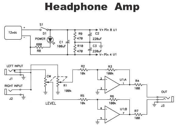
I have come across a schematic for a headphone amp and was wondering if anyone could have a look at it and verify that it is a proper circuit. Any suggestions as to the best chip to use as U1 would be appreciated. I would use this to drive full-sized headphones, not those little walkman type, and am looking for it to be as hi-fi as possible.

Also, could someone direct me to a listing of pot codes. I don't remember what the CW means on R1.

Thanks :wink:

Image
0 x

User avatar
Zeatle
Newbie
Newbie
Posts: 28
Joined: Thu 07/22/04 2:00 am
Location: Detroit, MI
Contact:

Post by Zeatle »

I know this is a little off the topic of 18 watt tube amps but I figured there would be someone here with knowledge of simple audio circuits.

I have found out that the chip for U1 should be a 5532 Dual OpAmp

As for the CW at R1. C is the old code for log (audio taper) but I don't know what the W means. Maybe it's not a pot code at all and simply means "clockwise".
0 x

loverocker
Senior Amp Tech
Senior Amp Tech
Posts: 1677
Joined: Thu 06/19/03 2:00 am
Location: England
Contact:

Post by loverocker »

Yes, I'm pretty sure it means clockwise, and R1 would definitely be Log.

Can't help much on the circuit, though. It's simple and easy to make, though it's so simple, I wonder if the result would be worth the effort?

Thing that bugged me most about such 'simple' circuits is that they always worked out expensive when you'd factored in the cost of the power supply, enclosure, etc.

Good luck :)
0 x

Wannatone
Frequent poster
Frequent poster
Posts: 622
Joined: Wed 06/18/03 2:00 am
Location: Germany

Post by Wannatone »

How ´bout replacing those opamps with EL86´s? :lol:

Adrian
0 x

User avatar
Artie
Newbie
Newbie
Posts: 81
Joined: Thu 11/13/03 2:00 am
Location: Jacksonville, Florida USA
Contact:

Post by Artie »

Isn't that the circuit from the PAiA headphone amp?

I've never actually heard one, but its supposed to be reasonably good quality.
0 x

User avatar
Zeatle
Newbie
Newbie
Posts: 28
Joined: Thu 07/22/04 2:00 am
Location: Detroit, MI
Contact:

Post by Zeatle »

Yea, that's the PAiA.

I removed the other 5 outputs from the diagram to make it smaller.

Full schematic HERE
0 x

User avatar
coop
Unrated
Posts: 18
Joined: Wed 05/26/04 2:00 am
Location: North Central Massachusetts, USA

Just wondering...

Post by coop »

So each amp is an inverting stage with a voltage gain of (negative) 10. Then there's a 100 Ohm resistor in series with the output which, when it sees an 8 Ohm headphone, will reduce by a factor of about 10 the voltage at the load. I guess it's a lot like a voltage follower where you get a reduction in source impedance with little or no voltage gain.

If your headphones are indeed 8 Ohms, you might consider downsizing that 100 Ohm output series resistor. If your headphones are higher impedance you would require less reduction.

If the source signal was 1Vrms (2.828VPk-to-Pk) and the overall voltage gain was near unity then the power delivered to each headphone would be:
P = (E^2)/Z = 1/8 = 125mW

I guess that would be pretty loud in a decently efficient set of headphones.

I was wondering if you could put a guitar into a circuit like this. So for every 100mVrms of signal from the guitar, you'd get 12.5mW. And you'd get more if you fooled around with the output resistor (remembering the need for stability, etc., etc.)

Just ruminating... hopefully correctly...
Coop
0 x

User avatar
coop
Unrated
Posts: 18
Joined: Wed 05/26/04 2:00 am
Location: North Central Massachusetts, USA

Just ruminating... hopefully correctly...

Post by coop »

Whoops, for 100mVrms of signal from your guitar you'd get:
(assuming approximately unity voltage gain)

P = (E^2)/Z = (0.1^2)/8 = 0.01/8 = 1.25mW


For 400mVrms of signal from your guitar you'd get:

P = (E^2)/Z = (0.4^2)/8 = 0.16/8 = 20mW


For 500mVrms of signal from your guitar you'd get:

P = (E^2)/Z = (0.5^2)/8 = 0.25/8 = 31.25mW


When you double that to 1Vrms (1000mVrms) you're
doubling the voltage which will quadruple the power
and you'll get the 125mW.

Coop
0 x

User avatar
dc_danman
Newbie
Newbie
Posts: 67
Joined: Fri 05/09/03 2:00 am
Location: UK (Japan for 6 months)

Post by dc_danman »

First, I would like to know, are you plugging your guitar straight into this, or is it meant to be a mini hifi amp?
If your doing hifi, then you may want to use a LM386 as they alot more powerful than normal op-amps, and would provide alot more head-room (if there is such a term in hifi :P) than them as well.
Using for a guitar? well, you may want to add another op-amp stage stage before this, so that you get enough gain to here what your playing, over the sound coming from your strings :D
Are you to afraid of the high voltages in tube amps at the moment, and want to do some solid state stuff instead? dont worry, thats what I done. you pick up alot of knowledge from it to, despite the diffrences between solid state and tube.
But, if you wouldn't mind spending a bit more than what you would for that, I would suggest starting with battery operated tubes. I happen to have a schematic that runs a DL91 tube (1s4, as more commenly knowen) off of 3 volts, I doubt you could hurt yourself with that even if you tried :P Tell me if your interested..
0 x

User avatar
Artie
Newbie
Newbie
Posts: 81
Joined: Thu 11/13/03 2:00 am
Location: Jacksonville, Florida USA
Contact:

Post by Artie »

Its interesting that the schematic Zeatle posted is from their headphone distribution box. The schematic for their straight headphone amp is the exact same circuit, but includes an additional cap in the feedback loop, plus an input cap:

Image

(BTW - They're showing a mono input here.)

I wonder what the difference in performance or function would be?

Here's the webpage:

http://www.paia.com/headbuff.htm

Also, I believe they used the 5532 specifically becuase of its low noise and 350mw output.
0 x

User avatar
Zeatle
Newbie
Newbie
Posts: 28
Joined: Thu 07/22/04 2:00 am
Location: Detroit, MI
Contact:

Post by Zeatle »

dc_danman -

It would be used to distribute the line out of a mixer to several sets of headphones to be used as monitors during rehearsals/recording. (See Full Schematic)

It's not that I'm afraid of the voltages, etc. it's just that 1) my band is in need of this device and 2) I wanted to start with something simple (cheap)

Artie -

Another reason for the 5532 is "The circuit can operate from bipolar voltages from +/-5V to +/-18V and it is not absolutely necessary that the + and - supply voltages be the same magnitude. The superior supply voltage rejection of the IC allows operation with unregulated supplies."
0 x

User avatar
coop
Unrated
Posts: 18
Joined: Wed 05/26/04 2:00 am
Location: North Central Massachusetts, USA

headphone amp circuit

Post by coop »

Actually after looking over the circuit and realizing the supply rails are at +6V and -6V, I realize the maximum power output of this circuit would be about 45mW.

Vout-opamp = 12V Pk-to-Pk = 6V Pk = 4.24Vrms

That means, with a voltage gain of 10,

Vin-opamp-max = 424mVrms (after that you're hard limiting,
of course, you have the potentiometer).

Maximum power output would be to a 100 Ohm load so,

Vout-load = 4.24Vrms / 2 = 2.12Vrms, and

Pout = (2.12^2)/100 = 45mW

In amateur radio circuits that would be a strong headphone signal. Is it enough for guitar/audio equipment purposes?

Coop
0 x

User avatar
Artie
Newbie
Newbie
Posts: 81
Joined: Thu 11/13/03 2:00 am
Location: Jacksonville, Florida USA
Contact:

Re: headphone amp circuit

Post by Artie »

coop wrote:Vout-load = 4.24Vrms / 2 = 2.12Vrms . . .
I'm not sure why you're including this step, which doesn't fit with my understanding of the math.

It should simply be 4.24V ^2/100 = 180 mw.

Add in an 8-ohm headphone, and that drops to around 166 mw.

And, if you build it with an 18 volt power supply, you'ld get the full 350 mw out. :wink:
0 x

User avatar
zaphod_phil
Builder, Admin
Builder, Admin
Posts: 15208
Joined: Wed 03/19/03 2:00 am
Location: YYZ

Post by zaphod_phil »

I hate to say it, but seeing all this opamp stuff is really giving me a bad feeling in my stomach.... :crazy:
0 x
Nature abhors a clean tube amp

User avatar
coop
Unrated
Posts: 18
Joined: Wed 05/26/04 2:00 am
Location: North Central Massachusetts, USA

Output Voltage

Post by coop »

The 4.24Vrms is the output voltage of the opamp itself.
Let's pretend the opamp has very low internal output impedance.
The 100 Ohm resistor can be though of as the output impedance of the overall amp circuit.
Maximum power transfer would be to a matched load of about 100 Ohms.
So the opamp's output voltage would be cut in half to 2.12Vrms at the load.
Thus the resulting power delivered to the load is:

Pload = (2.12^2)/100 ~= 45mW

That why I suggested that one could probably lower that 100 Ohm series resistor. In doing that you could increase the power delivered to the load. In the example above another 45mW is being dissipated in the 100 Ohm series resistor.

Another way to increase power to the load would be to use two opamps phase inverted driving the headphones "push-pull". Of course, you'd have to float the load apart from circuit ground or use a transformer.

Coop
0 x

User avatar
Artie
Newbie
Newbie
Posts: 81
Joined: Thu 11/13/03 2:00 am
Location: Jacksonville, Florida USA
Contact:

Post by Artie »

Ah yes . . . you're absolutely correct. :oops:

I forgot about MPT. Using my 8-ohm headphone example, you would, in fact, have approx. 166 mw output . . . 154 mw of which would be dropped across the internal 100 ohm resistor, leaving 12 mw for the headphones.

So, I wonder why they use that 100 ohm resistor in there? :cry:

I wonder how it would react if you changed it to 8?
0 x

User avatar
zaphod_phil
Builder, Admin
Builder, Admin
Posts: 15208
Joined: Wed 03/19/03 2:00 am
Location: YYZ

Post by zaphod_phil »

Or how about building a tiny Marshall amplifier, as this is a Marshall-related site? I'm thinking of the Marshall MS-2 "Micro Stack"- "... the MS-2 weighs vitually nothing, is extremely handy and sounds great." - Justine Frischmann / Elastica

Here's the schem - enjoy! :)
0 x
Nature abhors a clean tube amp

User avatar
coop
Unrated
Posts: 18
Joined: Wed 05/26/04 2:00 am
Location: North Central Massachusetts, USA

Headphone amp and output power

Post by coop »

Why is the 100 Ohm resistor in there?

I'm not an analog designer but some of these opamps
have difficulty driving a very low impedance load
especially if it has a reactive component. Swamping
the reactance component of load impedance may be
the purpose of the resistor. And it may also help
provide flat frequency response.

By the way, I just did a quick scan on the web and
found that 2 channels x 3mW seems to be the standard
for portable CD players! I didn't realize it was that
low. So 45mW into a set of earphones/headphones
must be plenty (~9dB louder for the same load!)


Anyway, Zeatle, I would encourage you to build the circuit.
Radio Shack has little project boards and boxes which
would be just about right for this circuit. You can find
sockets for the 8-pin DIP NE5532 (solder to the socket,
not the actual chip). Take your time and research
contruction techniques. You did indeed pick a really
useful function and after you're happy with the first,
you may wind up wanting to build a couple/few.

And Zaphod_Phil, thanks for sharing that neat circuit.

Coop
0 x

User avatar
Artie
Newbie
Newbie
Posts: 81
Joined: Thu 11/13/03 2:00 am
Location: Jacksonville, Florida USA
Contact:

Post by Artie »

I think I'm going to build one also, but with one slight mod - I'm going to use two NE5534's instead of the dual unit, just for the sake of having two discreet channels. Might give a little better heat dissipation. Or, it may not be significant.

I just prefer to it that way. :wink:
0 x

User avatar
dc_danman
Newbie
Newbie
Posts: 67
Joined: Fri 05/09/03 2:00 am
Location: UK (Japan for 6 months)

Post by dc_danman »

Well, as a n owner of an ms-2, I'd have to give my opinion on it :P :
pros:
1)its light.

cons:
1)The MS-2 lacks any form of decent overdrive
2)my headphones (cheap, not that good) have a better quality 'transducer' in them
3)You know how with tube amps, the amp can be, like 1 watt, but you can quite easily beleive its like 20 watt, well, this is solid state. it is half a watt, and it sounds like half a watt.
4)You'll be playing and someone will tell you its not switched on, that clean signal you thought you heard was just your strings :D
5)Its just marshall propoganda, and cost about £1.20 to make
6)This op-amp based headphone amp will be far better than it, when you consider:
You have ears, they do a good job for you, its only right you return the favour wereever possible.
The part are easy to obtain
its as bloody simple as it gets
overdriving your mixed music signal does not sound so good.

Just my humble opinion, that Im sure no-one will even bother to read :P
But phil, if I had a few quid, and about a few hours, Im sure I'd make one, just for the fun of it :D were'd you get the schematic, out of interest..
0 x

Post Reply