Advice needed...
Moderators: JMPGuitars, zaphod_phil, Daviedawg, Graydon, CurtissRobin, colossal
-
The4thWatcher13
- Occasional poster

- Posts: 142
- Joined: Sun 03/14/21 9:57 pm
Re: Advice needed...
Okie dokie, the Hammond chassis has arrived. I've only had a little time to consider how this should be laid out on the chassis and the circuit inside. While I was in storage I came a cross some old proto parts. Not sure if they'll be useful or not. The chassis is 6" deep, 8" wide & 2" thick. As I mentioned previously I also purchased some 47uF/160V axial caps, 3 or 4 of which could replace the multi-cap should another need to be added for the 6AV6 that was added. There should be ample real estate inside this chassis I think. The chassis has a rather robust plastic "scratch" cover on it which it seems is placed there so you can mark-up holes and do the work and not scratch up the surface in the process. I'm really not too sure where to start so I'm checking out pics of the work others have done on small amps first and reading all I can. Busy weekend but I'm back at it!
You do not have the required permissions to view the files attached to this post.
1 x
"Things are only impossible until they are not!" - Jean-Luc Picard.
-
TriodeLuvr
- Frequent poster

- Posts: 616
- Joined: Tue 10/16/18 11:19 am
Re: Advice needed...
Ahhh - flea clips! Haven't seen those in years. You should definitely replace the existing multi-cap. It's a senior citizen. 
Jack
Jack
1 x
-
The4thWatcher13
- Occasional poster
- Posts: 142
- Joined: Sun 03/14/21 9:57 pm
Re: Advice needed...
"Flea-clips" indeed. I bought an organ repair company years ago and there was all kinds of super neat old stuff like this. There were a bunch of clips in the boards shown and I pulled out the schnockerd ones. They fit in there quite tightly indeed. Is there any drawback to using these? Not sure if there will be any reason to do so on a small project like this but I just thought I'd ask. Also, currently I've got the type of 9 pin sockets that you can't use shields with. I'm gonna order up the shielded versions. (Why didn't I think of this last week?!)TriodeLuvr wrote: ↑Sun 04/18/21 8:13 pmAhhh - flea clips! Haven't seen those in years. You should definitely replace the existing multi-cap. It's a senior citizen.
0 x
"Things are only impossible until they are not!" - Jean-Luc Picard.
-
The4thWatcher13
- Occasional poster
- Posts: 142
- Joined: Sun 03/14/21 9:57 pm
Re: Advice needed...
One more thing... I'm wondering if any 6AV6 modifications/experiments with the current circuit would be easier to do now as opposed to inside of the chassis. Yes I've still got the super annoying heater wiring hum but...
Just a thought.
(well..actually probably 6 of one 1/2 doz. of the other so...)
Just a thought.
(well..actually probably 6 of one 1/2 doz. of the other so...)
0 x
"Things are only impossible until they are not!" - Jean-Luc Picard.
-
TriodeLuvr
- Frequent poster
- Posts: 616
- Joined: Tue 10/16/18 11:19 am
Re: Advice needed...
They need to be used with a proto board that has pads on the backside so they can be soldered in place. Not as sturdy as turrets, but there's no reason they couldn't be used on a small project.The4thWatcher13 wrote: ↑Sun 04/18/21 8:53 pm
"Flea-clips" indeed. I bought an organ repair company years ago and there was all kinds of super neat old stuff like this. There were a bunch of clips in the boards shown and I pulled out the schnockerd ones. They fit in there quite tightly indeed. Is there any drawback to using these?
I really like the standard J-slot US sockets and nickel-plated steel shields. Second best are the Russian ceramic sockets and aluminum shields (although they don't shield as well as the steel ones). The Chinese components sold by so many of the musical parts houses are garbage IMO.Also, currently I've got the type of 9 pin sockets that you can't use shields with. I'm gonna order up the shielded versions.
That's probably the last thing you'll ever need to do. The values used this stage are somewhat routine, and there's not much point to making changes.One more thing... I'm wondering if any 6AV6 modifications/experiments with the current circuit would be easier to do now as opposed to inside of the chassis.
Did you say you have a scope? If so, check the ripple to see if it's 60 Hz (heaters/grounding/shielding or 120 Hz (power supply ripple). Elevating the heaters is a good idea in any case, and it's easy to do.Yes I've still got the super annoying heater wiring hum but...
Jack
1 x
-
JMPGuitars

- Super Duper Admin

- Posts: 3967
- Joined: Tue 09/18/12 8:00 pm
- Location: South Central, MA
- Contact:
Re: Advice needed...
Belden Micalex sockets are excellent quality. By far better than the average ceramic sockets. Good ceramic sockets are expensive, and still easily damaged anyway.
These shields will fit over most standard noval sockets: https://www.amplifiedparts.com/products ... ple-colors
Thanks,
Josh
These shields will fit over most standard noval sockets: https://www.amplifiedparts.com/products ... ple-colors
Thanks,
Josh
0 x
'I installed a skylight in my apartment yesterday... The people who live above me are furious.' - Steven Wright
Modern Ground Schemes
Soldering Technique
B+ Voltage Reduction
Amplifier Tools & Parts Info
Web Design: DolceVittoria.com
Guitars / Amps / Effects: JMPGuitars.com
(anti)Social: Facebook · Instagram
Items for Sale
Modern Ground Schemes
Soldering Technique
B+ Voltage Reduction
Amplifier Tools & Parts Info
Web Design: DolceVittoria.com
Guitars / Amps / Effects: JMPGuitars.com
(anti)Social: Facebook · Instagram
Items for Sale
-
The4thWatcher13
- Occasional poster
- Posts: 142
- Joined: Sun 03/14/21 9:57 pm
Re: Advice needed...
Jack: Thanks for the info and recommendations. I'll be on that later today.
Josh: Thank you for the link. Those are actually the ones I ordered!
M
Josh: Thank you for the link. Those are actually the ones I ordered!
M
1 x
"Things are only impossible until they are not!" - Jean-Luc Picard.
-
The4thWatcher13
- Occasional poster
- Posts: 142
- Joined: Sun 03/14/21 9:57 pm
Re: Advice needed...
I cranked up the scope and started looking at the DC through the multi-cap toward the plates and screens and then the AC along the heater run but then I started hearing a quick tick, tick, tick, tick, tick..etc, that I've never heard before. This is without a guitar connected to the self grounding jack but a speaker is always connected. I've never run it without a load connected. I have a 8 ohm dummy load that I can use if that's better than a speaker.
Another thing I've been thinking about regarding the hum is that, in my readings, people talk about proper grounding. There are actually 4 separate points on the chassis that things are grounded to currently. I know this is a bad thing and have been considering a way to remedy it.
Another thing I've been thinking about regarding the hum is that, in my readings, people talk about proper grounding. There are actually 4 separate points on the chassis that things are grounded to currently. I know this is a bad thing and have been considering a way to remedy it.
0 x
"Things are only impossible until they are not!" - Jean-Luc Picard.
-
The4thWatcher13
- Occasional poster
- Posts: 142
- Joined: Sun 03/14/21 9:57 pm
Re: Advice needed...
This is the waveform that exists on the ground terminal of the speaker jack. Looks like 60 Hz. I'll have to poke around to see where it's coming from.
You do not have the required permissions to view the files attached to this post.
0 x
"Things are only impossible until they are not!" - Jean-Luc Picard.
-
TriodeLuvr
- Frequent poster
- Posts: 616
- Joined: Tue 10/16/18 11:19 am
Re: Advice needed...
Several things can cause 60 Hz hum, as you already know. Grounding issues can be difficult to troubleshoot, especially in a one-off build that hasn't been vetted by previous builders. Before you go down that road, it might be easier to first determine whether this is the heaters. You can substitute a 6V DC source temporarily to check this. Four D cells in series should be enough to light the tubes for a test. Consider the batteries throwaways, the cost of doing business. If this fixes the symptom, the problem is either a defective tube that's coupling from the heater to the cathode, or it's pickup (radiation) from the heater wiring to the signal path. The former is more common than you might think. Many a good tech has spent hours trying to find the cause of hum when it was actually one of the tubes. Pickup from the wiring can be detected by moving the wiring around and noting changes in hum level. It's also possible the lack of a shield on the 6AV6 is to blame. You could wrap some foil around the tube and touch it to the chassis for a test. Don't forget, also, that aluminum shielding won't help regarding magnetic induction. If the 6AV6 is too close to the power transformer, you'll need a traditional iron shield. It would help at this point if you could post a pic of the chassis.
Jack
Jack
1 x
-
JMPGuitars
- Super Duper Admin
- Posts: 3967
- Joined: Tue 09/18/12 8:00 pm
- Location: South Central, MA
- Contact:
Re: Advice needed...
The4thWatcher13 wrote: ↑Mon 04/19/21 7:52 pmAnother thing I've been thinking about regarding the hum is that, in my readings, people talk about proper grounding. There are actually 4 separate points on the chassis that things are grounded to currently. I know this is a bad thing and have been considering a way to remedy it.
1 x
'I installed a skylight in my apartment yesterday... The people who live above me are furious.' - Steven Wright
Modern Ground Schemes
Soldering Technique
B+ Voltage Reduction
Amplifier Tools & Parts Info
Web Design: DolceVittoria.com
Guitars / Amps / Effects: JMPGuitars.com
(anti)Social: Facebook · Instagram
Items for Sale
Modern Ground Schemes
Soldering Technique
B+ Voltage Reduction
Amplifier Tools & Parts Info
Web Design: DolceVittoria.com
Guitars / Amps / Effects: JMPGuitars.com
(anti)Social: Facebook · Instagram
Items for Sale
-
The4thWatcher13
- Occasional poster
- Posts: 142
- Joined: Sun 03/14/21 9:57 pm
Re: Advice needed...
Sorry, I needed to change this around. I'm having a "day"!
I swapped around and clarified what was previously written and added pics.
I swapped around and clarified what was previously written and added pics.
I have a regulated DC voltage supply on the bench (70V-1.5A), will that work just as well at the batteries? I'm assuming that you're saying replace the AC transformer for the heaters with the 6V DC, ..yes?TriodeLuvr wrote: ↑Mon 04/19/21 11:25 pm...it might be easier to first determine whether this is the heaters. You can substitute a 6V DC source temporarily to check this. Four D cells in series should be enough to light the tubes for a test...
Did you mean ..."if this doesn't fix the problem"?TriodeLuvr wrote: ↑Mon 04/19/21 11:25 pmIf this fixes the symptom, the problem is either a defective tube that's coupling from the heater to the cathode, or it's pickup (radiation) from the heater wiring to the signal path.
The pre tubes aren't that close to the transformers I'd say, but most the of transformers I see in amps have "bell" housings and these do not.TriodeLuvr wrote: ↑Mon 04/19/21 11:25 pmIf the 6AV6 is too close to the power transformer, you'll need a traditional iron shield. It would help at this point if you could post a pic of the chassis.
You do not have the required permissions to view the files attached to this post.
Last edited by The4thWatcher13 on Tue 04/20/21 10:01 pm, edited 1 time in total.
0 x
"Things are only impossible until they are not!" - Jean-Luc Picard.
-
TriodeLuvr
- Frequent poster
- Posts: 616
- Joined: Tue 10/16/18 11:19 am
Re: Advice needed...
Yes, use the bench supply if it will provide enough current. Remove the filament wires from the power transformer temporarily and power the tubes from your bench supply. See if this reduces the hum.
Jack
Jack
0 x
-
The4thWatcher13
- Occasional poster
- Posts: 142
- Joined: Sun 03/14/21 9:57 pm
Re: Advice needed...
Thanks Jack, I got it. But I'll have to pick up again tomorrow. I'm kinda fried for the day. Tuesdays...brutal!TriodeLuvr wrote: ↑Tue 04/20/21 9:42 pmYes, use the bench supply if it will provide enough current. Remove the filament wires from the power transformer temporarily and power the tubes from your bench supply. See if this reduces the hum. Jack
0 x
"Things are only impossible until they are not!" - Jean-Luc Picard.
-
The4thWatcher13
- Occasional poster
- Posts: 142
- Joined: Sun 03/14/21 9:57 pm
Re: Advice needed...
I've been checking out your link Josh and thanks! I've made some changes and it did improve a bit. I'm kinda toast today so I'll pick up again tomorrow (Wed) Thanks!JMPGuitars wrote: ↑Tue 04/20/21 7:19 amthe ground scheme thread in my signature. Follow the scheme there.
1 x
"Things are only impossible until they are not!" - Jean-Luc Picard.
-
TriodeLuvr
- Frequent poster
- Posts: 616
- Joined: Tue 10/16/18 11:19 am
Re: Advice needed...
LOL, I know what you mean. I just finished cutting a chassis for a new hi-fi amp. I had to rotate and re-register it four times on my small mill, plus add a spindle extension for one of the cuts. I'm beat!
Jack
Jack
3 x
-
The4thWatcher13
- Occasional poster
- Posts: 142
- Joined: Sun 03/14/21 9:57 pm
Re: Advice needed...
Jack: that is an awesome chassis job! I can't wait to see it when it's done. Queston: do you bolt or rivet your sockets to the chassis? I assume that your transformers are bolted down. As I mentioned in my reply to Josh, I made some grounding changes and re-twisted my heater wiring. The hum decreased a good deal and I'm actually rather happy with the sound this monstrosity is producing. Especially through the 12" fender cab. I'll almost surely be leaving the original 8" speaker behind and going for a larger driver. This amp can definitely push it. And although I've taken note of all of the recommendations for reducing the hum I'm going end my trouble shooting of that issue here and concentrate on the transfer to the new chassis. Aiming to become a better troubleshooter is never time wasted but at this point it's about to be gutted and swapped so considering the new layout seems more important to me at this point. If there are important things that I really should deal with at this point please let me know.
I know that this is in many ways different from a "traditional" conglomeration of guitar amp parts but I'm sure there are many "rules of thumb" that will apply when it comes to considering a layout scheme. I started creating a template for part placement all the while considering commonalities I've seen in similar amps but I've yet to really run across a "primer" for amp layout. I'm on the search again today. The last of the parts will be here Friday (shielded tube sockets, stand offs, etc.(fingers crossed) ..and some double sided "BusBoard" arrived today. Little by little we're getting there.
I know that this is in many ways different from a "traditional" conglomeration of guitar amp parts but I'm sure there are many "rules of thumb" that will apply when it comes to considering a layout scheme. I started creating a template for part placement all the while considering commonalities I've seen in similar amps but I've yet to really run across a "primer" for amp layout. I'm on the search again today. The last of the parts will be here Friday (shielded tube sockets, stand offs, etc.(fingers crossed) ..and some double sided "BusBoard" arrived today. Little by little we're getting there.
0 x
"Things are only impossible until they are not!" - Jean-Luc Picard.
-
The4thWatcher13
- Occasional poster
- Posts: 142
- Joined: Sun 03/14/21 9:57 pm
Re: Advice needed...
Note: I'm finding some good info online about chassis layout, wiring etc! Who'd a thunk it?! 
0 x
"Things are only impossible until they are not!" - Jean-Luc Picard.
-
TriodeLuvr
- Frequent poster
- Posts: 616
- Joined: Tue 10/16/18 11:19 am
Re: Advice needed...
I agree, it's time to build your amp on the new chassis, then perform final troubleshooting. I've always used screws for tube sockets, but rivets should work. In fact, I almost used rivets in the current project. They have a lower profile than pan head screws, and some octal sockets are designed for this. If normal screws are used, the bottom of the tubes can end up resting on the screw heads, not the socket. Not a problem with 9-pin and 7-pin minis like you're using.
You'll be OK if you design the layout left to right, just like the schematic. That helps to prevent the possibility that wires carrying high level signals will cross over and couple to low-level stages. Locate all the transformers away from the input stage (6AV6). Regarding the transformers themselves, mount the power (isolation) transformer farthest from the amplifier circuitry, then the filament transformer and audio output. It's generally OK if the power and filament transformers are in the same plane, but the audio transformer should be at right angles to both of them. Follow Josh's advice on grounding and you'll be OK.
FWIW, I twist filament wiring, but I don't follow the usual practice of tucking it down onto the chassis or into corners. Balanced cable (e.g. twisted wire) becomes unbalanced and subject to radiating its currents if it's in close proximity to other conductors. So, I prefer to elevate it physically and keep all the single-ended wiring, including signal carrying wires and components, down against the chassis. This isn't a critical aspect of building an amp, just my preference. If it was critical, most guitar amps would hum like mad.
Jack
3 x
-
The4thWatcher13
- Occasional poster
- Posts: 142
- Joined: Sun 03/14/21 9:57 pm
Re: Advice needed...
Got it. Great advice, thank you Jack! By this logic the heater wiring would be the last wiring to install, yes?TriodeLuvr wrote: ↑Wed 04/21/21 8:43 pmFWIW, I twist filament wiring, but I don't follow the usual practice of tucking it down onto the chassis or into corners. Balanced cable (e.g. twisted wire) becomes unbalanced and subject to radiating its currents if it's in close proximity to other conductors. So, I prefer to elevate it physically and keep all the single-ended wiring, including signal carrying wires and components, down against the chassis. This isn't a critical aspect of building an amp, just my preference. If it was critical, most guitar amps would hum like mad.
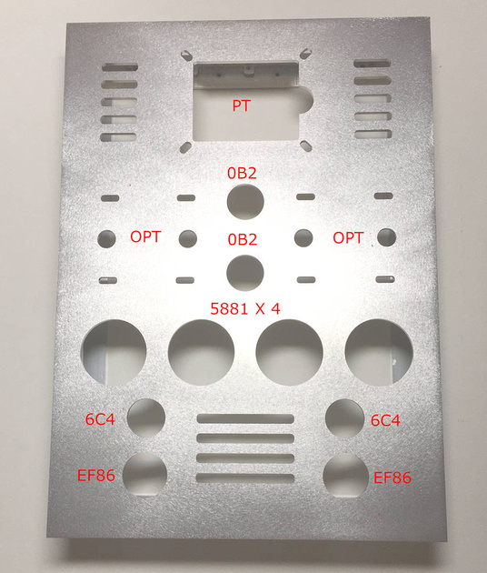
There's a lot of stuff out there regarding amp layouts, lots of build pics and lot's of good advice. I've included a pic, to scale, of the first basic layout. Anything could go either way at this point. As a guy that tries to get things "right" the first time this is terrifying!
You do not have the required permissions to view the files attached to this post.
Last edited by The4thWatcher13 on Thu 04/22/21 2:16 pm, edited 4 times in total.
0 x
"Things are only impossible until they are not!" - Jean-Luc Picard.