Good, 'cause I'm fixin' to build one! I haven't decided on the 12AU7 CF's yet, might add a bit of softness to the pi distortion though....
Cool thing about this build (hopefully) is that the datasheets suggest a 6K6 load at 450 for cathode biased EL34's, with 470 ohm cathode resistors. I hope to run a GZ34 for EL34's, with the option to pop in a 5U4G for 6L6's which also want 6K6 load and 470 Rk's, or you can run a 5Y3 and a pair of 6V6's, without changing a thing, and get a 5E3 type output stage. Fingers crossed, but as long as it works out with the EL34's, I think I'll be pretty happy.
36 Watt with EL-34
Moderators: zaphod_phil, Daviedawg, Graydon, CurtissRobin, colossal
-
klingo

- Occasional poster

- Posts: 214
- Joined: Sun 05/21/06 2:00 am
- Location: Corsica
-
zaphod_phil

- Builder, Admin

- Posts: 15208
- Joined: Wed 03/19/03 2:00 am
- Location: YYZ
You can tie them together, but EL34s work even better (at least in theory) if you bias the suppressor grid negatively relative to the cathode. So the recommendation is to connect the pin to ground in cathode-biased amps. It's also recommended to use two separate cathode resistors with bigger tubes like EL34s, or you will end up having to dissipate a lot of power through just one.
IIRC the challenge with this approach is that you would need a bipolar power supply for the two CFs.Alexo wrote:Good, 'cause I'm fixin' to build one! I haven't decided on the 12AU7 CF's yet, might add a bit of softness to the pi distortion though....
0 x
Nature abhors a clean tube amp
-
sub
- Frequent poster

- Posts: 811
- Joined: Thu 03/23/06 2:00 am
- Location: Europe
Thank you Phil!zaphod_phil wrote:You can tie them together, but EL34s work even better (at least in theory) if you bias the suppressor grid negatively relative to the cathode. So the recommendation is to connect the pin to ground in cathode-biased amps. It's also recommended to use two separate cathode resistors with bigger tubes like EL34s, or you will end up having to dissipate a lot of power through just one.
What you think, if pin1 ground directly, sound will be little bit more fixed biased-ish <
...and if i not wrong this is not work on 6L6, 6V6... and similar beam tetrode because p1 and p8 is tied together.. correct?
Here is two sketch:
first: "standard"
secound: "pin1 directly ground"
(please correct me if anything is wrong.... thanks)
0 x
-
morcey2
- Frequent poster
- Posts: 705
- Joined: Tue 06/06/06 2:00 am
- Location: Utah
The beam tetrodes won't care because pin 1 isn't used on them at all. The beam-formers are tied internally to the cathode which then connects to pin 8.sub wrote: Thank you Phil!
What you think, if pin1 ground directly, sound will be little bit more fixed biased-ish <(sorry i cant find the right word
)
...and if i not wrong this is not work on 6L6, 6V6... and similar beam tetrode because p1 and p8 is tied together.. correct?
I usually do any octal power tube sockets for cathode-biased amps with pin-1 to ground and pin-8 to the cathode resistor (oddball tubes excluded 7591, 7027, etc).
Matt
0 x
-
sub
- Frequent poster
- Posts: 811
- Joined: Thu 03/23/06 2:00 am
- Location: Europe
Ohh i got itmorcey2 wrote:The beam tetrodes won't care because pin 1 isn't used on them at all. The beam-formers are tied internally to the cathode which then connects to pin 8.
Thank you Matt!
I looked over few cathode biased EL34 amp schem... all of them use, pin1 and pin8 tied together then connects to res/cap... why? Maybe these schem isn't indicate every detail correctly?I usually do any octal power tube sockets for cathode-biased amps with pin-1 to ground and pin-8 to the cathode resistor (oddball tubes excluded 7591, 7027, etc).
Matt
What do you think, what is the difference between two method, sound or rather reliability?
Sorry about my too much question... but i should like to understand these stuffs...
0 x
-
zaphod_phil
- Builder, Admin
- Posts: 15208
- Joined: Wed 03/19/03 2:00 am
- Location: YYZ
Supposedly, you get slightly more electron flow through the tube with the suppressor grid biased negative relative to the cathode. That's why EL34s have the external pin for the suppressor grid. I've heard it also increases tube lifetime as well (according to Tone Lizard).... I don't have a lot more definate information than that, but it's enough for me to build amps with the pin 1 grounded if cathode-biased, or connected to the -ve bias supply, if fixed-bias..
0 x
Nature abhors a clean tube amp
-
tubetek
- Occasional poster
- Posts: 204
- Joined: Wed 02/04/04 2:00 am
- Location: Red River Gorge, Kentucky
Check out Traynor's history...
Peter Traynor did just what we are talking about here (following Mullard's recommendations) AND using pretty insane B+. His amps were legendary for reliability and output power; my old YBA-1 Bassmaster was the most powerful 2xEL34 amp I've ever experienced. Kevin O'Connor goes into a detailed (if somewhat gushing) explanation in TUT-1. Remember, Mullard rated the '34 to handle 800VDC on the plate; Traynor commonly ran 560 and up in his designs and they lived! (at least with good NOS tubes) If there was any complaint, it was that his designs were too "clean" sounding.
Tom
0 x
-
hkwijhe
- Unrated
- Posts: 2
- Joined: Fri 05/23/08 2:00 am
- Location: Wijhe (Netherlands)
new schematic
Hi all,
Please find attached a schematic I have designed. It is based on the trainwreck with a few additions/changes:
- power scaling
- ppi master volume
- kathode follower before tone stack
Please let me know what you think of it !!!
Hans
Please find attached a schematic I have designed. It is based on the trainwreck with a few additions/changes:
- power scaling
- ppi master volume
- kathode follower before tone stack
Please let me know what you think of it !!!
Hans
0 x
-
stevesuk
- Frequent poster
- Posts: 893
- Joined: Sat 07/19/03 2:00 am
- Location: UK
- Contact:
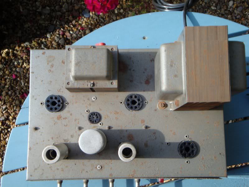
Perfect candidate donor for a 36 Watt EL34's
If I can find the time I may just try the 36Watt variant suggested here.
The attached photo shows a donor just crying out to be modified (rebuilt).
Probably leave the layout as is.
Steve UK
www.valvepower.co.uk
The attached photo shows a donor just crying out to be modified (rebuilt).
Probably leave the layout as is.
Steve UK
www.valvepower.co.uk
0 x
-
Alexo
- Verbose poster
- Posts: 1676
- Joined: Thu 09/21/06 2:00 am
- Location: Upstate NY, USA
-
sub
- Frequent poster
- Posts: 811
- Joined: Thu 03/23/06 2:00 am
- Location: Europe
Thanks!Alexo wrote:Good luck! I think you'll be happy with the amount of gain.
I have no choise, i have a 50W Marshall style PT without any rectifier heater tap. Fortunately the PT is a "low voltage" version (310-0-310).If I had to do it again, I'd go with an ss rectifier, but that's just my personal preference.
I think i will get about 390-410V B+ with SS rectifier...
This is a "good news" for me > you suggest SS recto
[/quote]
0 x
-
sub
- Frequent poster
- Posts: 811
- Joined: Thu 03/23/06 2:00 am
- Location: Europe
-
klingo
- Occasional poster
- Posts: 214
- Joined: Sun 05/21/06 2:00 am
- Location: Corsica
Hi Sub,
check the bible http://www.mif.pg.gda.pl/homepages/fran ... e/EL34.pdf
this Mullard EL34 datasheet say on page 3
B+ 375v>Rk 260R each /Rg2 470R common
B+ 450v>Rk 465R each /Rg2 1K common
Rg2 is a non decoupled resistor common to both valves (like the 100R in a 18W)
two cathode resistors around 400R seem ok with your voltage
check the bible
this Mullard EL34 datasheet say on page 3
B+ 375v>Rk 260R each /Rg2 470R common
B+ 450v>Rk 465R each /Rg2 1K common
Rg2 is a non decoupled resistor common to both valves (like the 100R in a 18W)
two cathode resistors around 400R seem ok with your voltage
0 x
-
sub
- Frequent poster
- Posts: 811
- Joined: Thu 03/23/06 2:00 am
- Location: Europe
Ohhhklingo wrote:Hi Sub,
check the bible
this Mullard EL34 datasheet say on page 3
B+ 375v>Rk 260R each /Rg2 470R common
B+ 450v>Rk 465R each /Rg2 1K common
Rg2 is a non decoupled resistor common to both valves (like the 100R in a 18W)
two cathode resistors around 400R seem ok with your voltage
Thank you Klingo!
Thank you Alexo!Actually I think I used a 10 watt 360 ohm resistor on each cathode, and they biased the amp to about 85% max. plate dissipation. I had a choke-fed screen supply, btw..
I will try out everything between 300-400R
BTW M. Clubman with 430 B+ use 270R
0 x