Wiring Question (Answered)
Moderators: zaphod_phil, Daviedawg, Graydon, CurtissRobin, colossal
-
DH166
- Newbie

- Posts: 44
- Joined: Fri 11/06/20 3:42 pm
Re: Wiring Question (Answered)
So, opening this thread back up. About a week after my last post, I broke my wrist and the project got put on the shelf. Back at it now, though, and hoping to finish it once and for all over the next couple weeks. My question now is about the shielded wire from the input to V1. A couple of posts up the thread, you said to ground one end of the shielding, preferably near V1, and just heat shrink the other end. I put a terminal strip near V1 with one isolated lug and one grounded lug and wired up the hot wire through the isolated lug to the 10K resistor on pin 2. Then, I soldered the shielding to the grounded lug on the terminal. Problem is that I now have continuity between the two. Obvious answer is that I have a short in the wire itself, that I did a poor job stripping and separating it. However, before I start over with a new strand of wire, I just want to make sure that I wired it up correctly. Picture is below.
You do not have the required permissions to view the files attached to this post.
2 x
-
Unit_1

- Newbie
- Posts: 32
- Joined: Sun 11/09/14 6:35 pm
Re: Wiring Question (Answered)
It's kinda blurry, and my old eyes have a hard time seeing blurry, but it does look ok. I usually ground at the input jack side since there's already a ground available, never any problems whatsoever.
You can't even tell my Hiwatt DR504 is on until you hit a string and then everyone in the room jumps a foot off the ground 'cuz it's so loud and unexpected.
I also use a very short length of shielding, only about 3/8" and I twist green insulated wire to this and solder before shrink wrapping it. Then I run the green wire to ground. Much easier and you're not stripping away a large amount of shielded wiring just to make a longer ground. Plus everything is now insulated, no chances of it ever touching anything.
You can see the green wire running out of the bottom of the blue shrink wrap, and can you imagine as crowded as this is how hard it would be to keep from touching something else?
https://postimg.cc/Ff6XqDss
1 x
The ability to play/make music is a gift that not everyone gets. Those of us who have it should use it.
-
DH166
- Newbie
- Posts: 44
- Joined: Fri 11/06/20 3:42 pm
Re: Wiring Question (Answered)
Thanks for the reply. I started over with a new length of wire and was extra careful stripping it to make sure I didn't puncture it anywhere and that no strands of braid were left touching anything. Problem is, I'm still grounded from the hot side that connects to V1. Now, I do also have a ground at the input jack. Not from the shielded wire, but just a length of wire between the outside most lug (tip, sleeve?). See pics (sorry, they attached upside down and I don't know how to flip them). Is that right? That ground should be there regardless of which end you ground the shielded wire, right? So, if you ground the shielding at the input, there'd be two connections to ground up there and none at the V1 end and if you did it like I did, there'd be one connection to ground at each end? Confused.
You do not have the required permissions to view the files attached to this post.
0 x
-
JMPGuitars

- Super Duper Admin

- Posts: 3965
- Joined: Tue 09/18/12 8:00 pm
- Location: South Central, MA
- Contact:
Re: Wiring Question (Answered)
Without a cable connected to the input jack, the input will be grounded if it's wired correctly. Insert a cable in the input jack and test again.
Sorry to hear about your wrist, I hope you're all healed up now!
Thanks,
Josh
Sorry to hear about your wrist, I hope you're all healed up now!
Thanks,
Josh
2 x
'I installed a skylight in my apartment yesterday... The people who live above me are furious.' - Steven Wright
Modern Ground Schemes
Soldering Technique
B+ Voltage Reduction
Amplifier Tools & Parts Info
Web Design: DolceVittoria.com
Guitars / Amps / Effects: JMPGuitars.com
(anti)Social: Facebook · Instagram
Items for Sale
Modern Ground Schemes
Soldering Technique
B+ Voltage Reduction
Amplifier Tools & Parts Info
Web Design: DolceVittoria.com
Guitars / Amps / Effects: JMPGuitars.com
(anti)Social: Facebook · Instagram
Items for Sale
-
Unit_1
- Newbie
- Posts: 32
- Joined: Sun 11/09/14 6:35 pm
Re: Wiring Question (Answered)
Are you maybe measuring 68K or 1M across that resistor to ground?
When checking for continuity you should have your ohms set to the lowest setting. Then touch both of the probes together. You should get a very low reading like .1 ohms. If you get more than that when you connect to a circuit, then a resistor in the circuit somewhere is involved.
Try inserting a 1/4" plug into the input jack and see if it changes, this should separate the leads of the switch on the jack.
I can't really see how everything is hooked up on the jack. But on my DR504 with no plug in the jack I measure 68k from pin 2 to ground, which is as it should be.
1 x
The ability to play/make music is a gift that not everyone gets. Those of us who have it should use it.
-
DH166
- Newbie
- Posts: 44
- Joined: Fri 11/06/20 3:42 pm
Re: Wiring Question (Answered)
Got it! Thanks for the response. So, now I'm starting on the turret board. I know that the outside foil end on my caps is meant to face the lower impedance side of the circuit. I have no idea how to identify that on the layout or schematic, though. What do I look for?
2 x
-
JMPGuitars
- Super Duper Admin
- Posts: 3965
- Joined: Tue 09/18/12 8:00 pm
- Location: South Central, MA
- Contact:
Re: Wiring Question (Answered)
Ground or the previous stage's plates, whichever is closer/has less resistance. This schematic is a different circuit, but it should give you an idea: files/JMPGuitars_18_Watt_Tremolo_TMB_Re ... ematic.pdfDH166 wrote: ↑Tue 06/14/22 3:28 pmGot it! Thanks for the response. So, now I'm starting on the turret board. I know that the outside foil end on my caps is meant to face the lower impedance side of the circuit. I have no idea how to identify that on the layout or schematic, though. What do I look for?
Are your caps marked for foils, or did you mark them using a scope?
Thanks,
Josh
1 x
'I installed a skylight in my apartment yesterday... The people who live above me are furious.' - Steven Wright
Modern Ground Schemes
Soldering Technique
B+ Voltage Reduction
Amplifier Tools & Parts Info
Web Design: DolceVittoria.com
Guitars / Amps / Effects: JMPGuitars.com
(anti)Social: Facebook · Instagram
Items for Sale
Modern Ground Schemes
Soldering Technique
B+ Voltage Reduction
Amplifier Tools & Parts Info
Web Design: DolceVittoria.com
Guitars / Amps / Effects: JMPGuitars.com
(anti)Social: Facebook · Instagram
Items for Sale
-
DH166
- Newbie
- Posts: 44
- Joined: Fri 11/06/20 3:42 pm
-
Unit_1
- Newbie
- Posts: 32
- Joined: Sun 11/09/14 6:35 pm
Re: Wiring Question (Answered)
as odd as it sounds, you can make an audible testing device! It has two alligator clips, an input jack and an on off switch.
You put the device next to a motor or neon light, anything EM noisy. Using the clips you hook up the cap and flip the switch on. Listen. Turn it off, flip the cap and turn it back on. (edited: AFTER plugging into your amp, you do the test)
The side that is the noisiest is not the foil end.
It would have been easier to use if I had a three way switch, but I didn't have one at the time.
fwiw, I have a very large supply of Astron paper in oil caps, they're almost impossible to tell which side is the foil end because they are SO quiet....
1 x
The ability to play/make music is a gift that not everyone gets. Those of us who have it should use it.
-
DH166
- Newbie
- Posts: 44
- Joined: Fri 11/06/20 3:42 pm
Re: Wiring Question (Answered)
Next question: On the trem TMB layout, there's a 10k resistor between pin 2 on V3 and the .022 cap that leads into the volume pot. That resistor isn't there on the schematic, however. I made my Mouser list off the schematic, so I don't have that 10k (and I don't do enough projects to have bins full of passives). Before I make a new order and pay eight bucks shipping for a seventy eight cent resistor, is that resistor necessary, or is it a mod of some sort? What does it do?
1 x
-
JMPGuitars
- Super Duper Admin
- Posts: 3965
- Joined: Tue 09/18/12 8:00 pm
- Location: South Central, MA
- Contact:
Re: Wiring Question (Answered)
That's an optional grid stopper resistor. You might not need it, but I would recommend building with the terminal strip as pictured in the layout, in case you need to add the resistor later.DH166 wrote: ↑Fri 07/15/22 7:00 pmNext question: On the trem TMB layout, there's a 10k resistor between pin 2 on V3 and the .022 cap that leads into the volume pot. That resistor isn't there on the schematic, however. I made my Mouser list off the schematic, so I don't have that 10k (and I don't do enough projects to have bins full of passives). Before I make a new order and pay eight bucks shipping for a seventy eight cent resistor, is that resistor necessary, or is it a mod of some sort? What does it do?
Thanks,
Josh
1 x
'I installed a skylight in my apartment yesterday... The people who live above me are furious.' - Steven Wright
Modern Ground Schemes
Soldering Technique
B+ Voltage Reduction
Amplifier Tools & Parts Info
Web Design: DolceVittoria.com
Guitars / Amps / Effects: JMPGuitars.com
(anti)Social: Facebook · Instagram
Items for Sale
Modern Ground Schemes
Soldering Technique
B+ Voltage Reduction
Amplifier Tools & Parts Info
Web Design: DolceVittoria.com
Guitars / Amps / Effects: JMPGuitars.com
(anti)Social: Facebook · Instagram
Items for Sale
-
DH166
- Newbie
- Posts: 44
- Joined: Fri 11/06/20 3:42 pm
Re: Wiring Question (Answered)
Got it. Thanks. I ordered it. Learning process. It's getting pretty close to done. Man, it's been a long process. Thanks a ton for all your advice.
3 x
-
DH166
- Newbie
- Posts: 44
- Joined: Fri 11/06/20 3:42 pm
Re: Wiring Question (Answered)
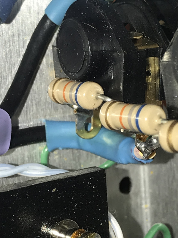
Next question: On the layout, the shielded wires are labeled, but on the notes it says to use shielded wire for the external footswitch. That one isn't labeled as shielded. So, should the wire that's purple in the picture, that goes from pin 7 on V1 through the tip lug on the switch and on to the 2.2M resistor, be shielded wire? If so, can the shielding be grounded at any point or is there a preferred place?
You do not have the required permissions to view the files attached to this post.
1 x
-
JMPGuitars
- Super Duper Admin
- Posts: 3965
- Joined: Tue 09/18/12 8:00 pm
- Location: South Central, MA
- Contact:
Re: Wiring Question (Answered)
I'd say it depends on your circumstances whether or not it really needs to be shielded. Shielded is probably safer. Ground the shield only on one side, I would use the ground lug on the terminal strip out of convenience.
2 x
'I installed a skylight in my apartment yesterday... The people who live above me are furious.' - Steven Wright
Modern Ground Schemes
Soldering Technique
B+ Voltage Reduction
Amplifier Tools & Parts Info
Web Design: DolceVittoria.com
Guitars / Amps / Effects: JMPGuitars.com
(anti)Social: Facebook · Instagram
Items for Sale
Modern Ground Schemes
Soldering Technique
B+ Voltage Reduction
Amplifier Tools & Parts Info
Web Design: DolceVittoria.com
Guitars / Amps / Effects: JMPGuitars.com
(anti)Social: Facebook · Instagram
Items for Sale
-
Bieworm

- Verbose Moderator

- Posts: 2302
- Joined: Mon 02/10/20 8:24 am
- Location: Belgium
Re: Wiring Question (Answered)
+1 on shielding those wires. I forgot to use shielded wires once there and ran into trouble. It was fixed when I changed them to a shielded type.
2 x
"THIS should be played at high volume..preferably in a residential area"
-
DH166
- Newbie
- Posts: 44
- Joined: Fri 11/06/20 3:42 pm
Re: Wiring Question (Answered)
Ok. Follow-up: Is it just the longer the wire that goes from V1 through to the board (the purple one in the layout) that needs to be shielded, or does that small wire that goes from the tip lug on the switch itself over to the insulated terminal (the blue one in the above pic) also need to be shielded wire?
1 x
-
JMPGuitars
- Super Duper Admin
- Posts: 3965
- Joined: Tue 09/18/12 8:00 pm
- Location: South Central, MA
- Contact:
Re: Wiring Question (Answered)
There was no pic in your post, but if you're referring to the light blue wire connecting to the tip if the switch JACK, then yes, that's the wire we're saying to use shielded wire for.DH166 wrote: ↑Sat 07/16/22 8:45 pmOk. Follow-up: Is it just the longer the wire that goes from V1 through to the board (the purple one in the layout) that needs to be shielded, or does that small wire that goes from the tip lug on the switch itself over to the insulated terminal (the blue one in the above pic) also need to be shielded wire?
The input jack to V1, V1 plates (p1 and p6), and the gain knob to V2 should all be shielded wires, in addition to the tremolo switch.
1 x
'I installed a skylight in my apartment yesterday... The people who live above me are furious.' - Steven Wright
Modern Ground Schemes
Soldering Technique
B+ Voltage Reduction
Amplifier Tools & Parts Info
Web Design: DolceVittoria.com
Guitars / Amps / Effects: JMPGuitars.com
(anti)Social: Facebook · Instagram
Items for Sale
Modern Ground Schemes
Soldering Technique
B+ Voltage Reduction
Amplifier Tools & Parts Info
Web Design: DolceVittoria.com
Guitars / Amps / Effects: JMPGuitars.com
(anti)Social: Facebook · Instagram
Items for Sale
-
DH166
- Newbie
- Posts: 44
- Joined: Fri 11/06/20 3:42 pm
Re: Wiring Question (Answered)
Thanks. Now, I may have been confused in the previous response. Prior to my last post, I was asking about the wire (purple in the layout) that goes from V1 p7 through the insulated terminal (at least it looks like it does) and onto the board to the 2.2M resistor. When I read the note about using shielded wire for the external switch, that's the wire I wondered about, but that one was not in the list of shielded wires in your last response. Is that wire shielded?
0 x
-
JMPGuitars
- Super Duper Admin
- Posts: 3965
- Joined: Tue 09/18/12 8:00 pm
- Location: South Central, MA
- Contact:
Re: Wiring Question (Answered)
It shouldn't be necessary. That wire should be very short, as pictured.DH166 wrote: ↑Sun 07/17/22 9:28 amThanks. Now, I may have been confused in the previous response. Prior to my last post, I was asking about the wire (purple in the layout) that goes from V1 p7 through the insulated terminal (at least it looks like it does) and onto the board to the 2.2M resistor. When I read the note about using shielded wire for the external switch, that's the wire I wondered about, but that one was not in the list of shielded wires in your last response. Is that wire shielded?
The wire running to the jack is typically much longer than pictured, that's why it often needs shielding.
1 x
'I installed a skylight in my apartment yesterday... The people who live above me are furious.' - Steven Wright
Modern Ground Schemes
Soldering Technique
B+ Voltage Reduction
Amplifier Tools & Parts Info
Web Design: DolceVittoria.com
Guitars / Amps / Effects: JMPGuitars.com
(anti)Social: Facebook · Instagram
Items for Sale
Modern Ground Schemes
Soldering Technique
B+ Voltage Reduction
Amplifier Tools & Parts Info
Web Design: DolceVittoria.com
Guitars / Amps / Effects: JMPGuitars.com
(anti)Social: Facebook · Instagram
Items for Sale
-
DH166
- Newbie
- Posts: 44
- Joined: Fri 11/06/20 3:42 pm
Re: Wiring Question (Answered)
Ok. Next question: Have a look at the picture. As I'm now at the point of connecting the valves to the board, I've got a lot of parallel wires, such as the green pair and yellow pair coming off V4 and V5, and I'm concerned about that. Are these going to be far enough apart to avoid issues, or should those wires be twisted?
You do not have the required permissions to view the files attached to this post.
0 x