Page 16 of 24
Posted: Sun 10/31/10 4:35 pm
by TWANG
goody goody goody
re: loud.
Posted: Mon 11/01/10 6:44 pm
by insanecopilot
As far as i can tell it looks good Dustpuppy. Nice layout, what do you use to make it?
Posted: Mon 11/01/10 8:31 pm
by Dustpuppy
Thanks guys, I used OpenOfficeOrg draw to build this. I built a template a while ago with all of the shapes so it's quicker to lay out.
Posted: Tue 11/02/10 10:55 pm
by Dustpuppy
Ok, the board is done. Here are a couple of shots.


Posted: Wed 11/03/10 10:21 am
by TWANG
nice!
Posted: Wed 11/03/10 5:07 pm
by StarGeezers
Posted: Fri 11/12/10 9:59 pm
by Dustpuppy
ok I finished my Abmin 18. First power up. the bass was way too loose. I swapped a 1000uF for the 220uF cathode bypass cap. Now you were right. This amp sounds SWEEET! I did also add a tweed tone stack. Thanks for turning me onto this one.
Now I'd like to turn this schematic into a high gain amp. what do you think would work better? A 6C4 as the second triode or another 6SJ7? Or, should I just add a 12AX7 for 2 more gain stages? I'm in option overload!
Brett
Posted: Sat 11/13/10 3:13 pm
by Dustpuppy
I've had some time to put this amp through it's paces. I am impressed with it's tonality. The sustain is amazing and I have never heard distortion like this. The tweed tonestack does a adequate job. The Geez is right, bloody loud!
Posted: Tue 11/16/10 11:57 am
by StarGeezers
Posted: Tue 11/16/10 12:25 pm
by TWANG
I just got my RF drive board!
Posted: Tue 11/16/10 1:04 pm
by StarGeezers
TWANG, There ya' go eh!!!!

Posted: Tue 11/16/10 5:46 pm
by TWANG
figuring out my parts order..
the 18 watt is the tortoise panel in the middle.
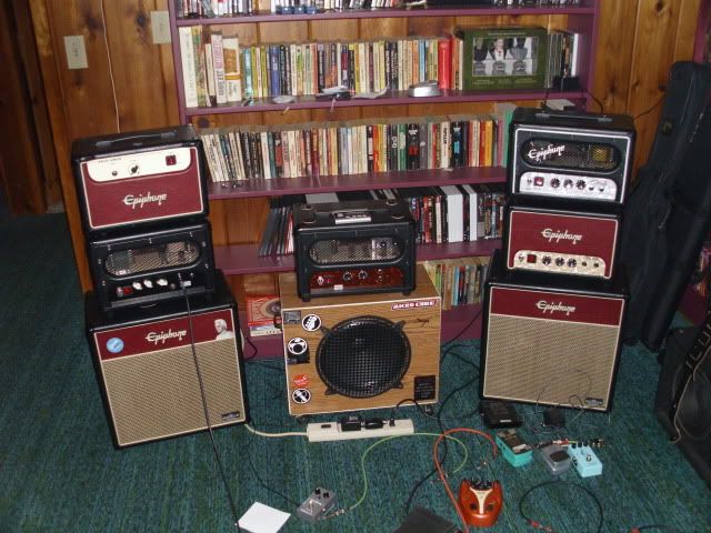
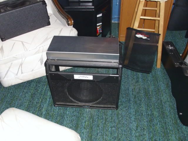
and I got my superlite chassis in today..
here's it and the raven combo cab I'll put it in..
still have to figure out how to lay it all in there..
Posted: Wed 11/17/10 8:01 am
by StarGeezers
Nice collection there TWANG !!! You may have to cut that chassis down a bit ... looks Close !!!
Posted: Wed 11/17/10 12:40 pm
by TWANG
She fits!
It's just sitting funny.
I got it 2 1/2" so it would clear the front top and bottom
and it's just right from side to side.
In the front the corner screws go right into the chassis lip, so I'll put bolt there.. and in the back, being 8" instead of 10".. I wanted the fuse holder to not stick out.. I'll add two bolts.
Still have to order some parts..got my bigger step bits coming..
Posted: Thu 11/18/10 11:42 am
by StarGeezers
If it fits , that's GOOD !!!

Posted: Sat 11/20/10 11:58 am
by TWANG
can't find the drill plan for II 2.7.
Spose I can make one.
I know I had an url. I think from sewatt... I'll look over there again.
Posted: Sat 11/20/10 9:04 pm
by zaphod_phil
More likely to have been from PPwatt.com
Posted: Sat 11/20/10 11:17 pm
by TWANG
looks like there isn't one.
have to make one after all..
still looking for a way to hook it up.. is all that in the schematic?
PT etc?
I'll take a look of course.
Posted: Sun 11/21/10 7:44 am
by zaphod_phil
I'm sure at least a few people must have kept a copy of the layout and build instructions. I don't think there's much chance of building one of those PCB amps correctly without the drawings. The schematics on this site are very generic and don't have any of the build details.
I understand the plan is to make these PCBs available again, and therefore all the documentation will be as well.
Posted: Sun 11/21/10 10:38 am
by xlch
Twang
This should be the Drill plan you need
http://rh-tech.org/public/z_stingray_pc ... n%20v1.pdf
If this is not correct your going to have to use your PCB to mark the holes out and drill to the correct size. I do have a couple of the PCBs here that I have not started on. I dont own a scanner but I can have them scans of both sides made if it will help people out.
The schematic shows how to wire up the transformers.
Here
http://rh-tech.org/public/z_stingray_pc ... c%20v3.pdf

