Re: Parasitic oscillation problem untraceable
Posted: Tue 01/05/21 4:26 pm
Yes, get rid of it! Do it now while you can. "Buy cheap, buy twice."
Tube Guitar Amp Discussion Forums
https://www.18watt.com/
Yes, get rid of it! Do it now while you can. "Buy cheap, buy twice."
You stated previously that the problem exists on both "channels."Bieworm wrote: ↑Tue 01/05/21 4:22 pmDon't have target voltages. I wish I had em... top secret tone king gear...
Why do you think It's the clean channel? They only share the 1st triode and PI etc..and that's fine. It situates between the 1st triode and the 3rd preamp triode of the OD channel according to the scope? Or am I reading the wavefirms wrong?
 Is it symmetrical, or is it distorted?
This sounds like a misunderstanding of your circuit. Look at your schematic more closely. They share the signal path any time the relay is activated. The relay section, that I assume noticeably increases your gain, can't exist without the "other" channel.They only share the 1st triode and PI etc..and that's fine.
 ya tomorrow
That voltage divider is backwards. Leave the 470K R20 in place, and add the 500K pot to ground after it.
I apologize, I'm really not trying to be disagreeable here, but that is false. Harmonics reside in the frequency domain. An unbalanced phase inverter changes amplitude, not frequency. The balance of the phase inverter has nothing to do with frequency nor harmonics.TriodeLuvr wrote: ↑Tue 01/05/21 1:38 pm
We were discussing a single frequency sinewave (per your illustration). Any distortion through a circuit that does not introduce an additional signal source at a different frequency can only consist of harmonic energy.
It's just a technical discussion, I'm OK with it.crgfrench wrote: ↑Tue 01/05/21 11:26 pmI apologize, I'm really not trying to be disagreeable here, but that is false. Harmonics reside in the frequency domain. An unbalanced phase inverter changes amplitude, not frequency. The balance of the phase inverter has nothing to do with frequency nor harmonics.TriodeLuvr wrote: ↑Tue 01/05/21 1:38 pm
We were discussing a single frequency sinewave (per your illustration). Any distortion through a circuit that does not introduce an additional signal source at a different frequency can only consist of harmonic energy.
 You're right about the phase inverter. It's Class A, and when it's unbalanced, that only means one anode has a different amplitude than the other. The problem occurs when the unbalanced signals drive the AB1 output stage. The output stage relies on the two drive signals to be equal and opposite in order to reproduce a correct sinewave. Each tube only amplifies the positive-going portion of the signal impressed on its grid, and the two positive-going waveforms from the two tubes (negative-going at the anodes) are applied alternately to the output transformer in push-pull.
My preference would be a good used scope made in the West, such as HP (Agilent), Tektronix, LeCroy, etc.Bieworm wrote: ↑Tue 01/05/21 4:13 pmNot really like crossover distortion 20210105_221143.jpgTriodeLuvr wrote: ↑Tue 01/05/21 3:18 pmI thought you didn't have a scope? What does it look like at the output (speaker)?
As for the scope... I just didn't know how to use it I guess. I bought it a couple of weeks ago... but I intended to bring it back. I kinda got the hang of it today... should I change it for the Siglent 1102 ?
It's with a dummy load on the output jack. But it should be seriously fizzing at the actual settings. Vol on 6 (max headroom is about vol 3) , tone on 5 and midbite on maxTriodeLuvr wrote: ↑Wed 01/06/21 3:06 amMy preference would be a good used scope made in the West, such as HP (Agilent), Tektronix, LeCroy, etc.Bieworm wrote: ↑Tue 01/05/21 4:13 pmNot really like crossover distortion 20210105_221143.jpgTriodeLuvr wrote: ↑Tue 01/05/21 3:18 pmI thought you didn't have a scope? What does it look like at the output (speaker)?
As for the scope... I just didn't know how to use it I guess. I bought it a couple of weeks ago... but I intended to bring it back. I kinda got the hang of it today... should I change it for the Siglent 1102 ?
About the waveform, is that pic showing the output of the amp when you hear the fizz? It looks like hard clipping, a waveform not too different from a solid state clipper. I agree, there's no crossover distortion of any significance.
Jack
It's not class A. Cathode bias doesn't make an amp Class A.
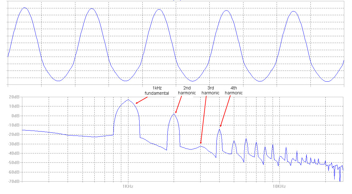
The phase inverter is Class A. The output stage is AB1. I modeled this in SPICE to produce an output waveform that makes the effect obvious. Below is what happens at the output when the phase inverter is unbalanced.JMPGuitars wrote: ↑Wed 01/06/21 7:14 amIt's not class A. Cathode bias doesn't make an amp Class A.
https://www.aikenamps.com/index.php/the ... on-class-a
Question: clean channel, is it better than it was or the same or worse? Same question for the OD channel?Bieworm wrote: ↑Wed 01/06/21 3:49 pmDisconnected reverb at point X.
Voltage divider at point X
C6 from .047 to .022uf
PI Tail resistor 30k
Fizz fizz fizz.
On OD channel across the entire sweep of the voltage divider
On clean channel on overdriven volume
This can't be the PI anymore!!! This has to be on the 1st preamp stage??
Clean ch I think is the sameJMPGuitars wrote: ↑Wed 01/06/21 7:22 pmQuestion: clean channel, is it better than it was or the same or worse? Same question for the OD channel?Bieworm wrote: ↑Wed 01/06/21 3:49 pmDisconnected reverb at point X.
Voltage divider at point X
C6 from .047 to .022uf
PI Tail resistor 30k
Fizz fizz fizz.
On OD channel across the entire sweep of the voltage divider
On clean channel on overdriven volume
This can't be the PI anymore!!! This has to be on the 1st preamp stage??
Post all your voltages, especially your PI. If the voltage dividers there didn't improve anything, then make the preamp section going to X completely stock per schematic (before taking new voltages).
That's very interesting, thanks! How did you get the 2:1 amplitude ratio to generate (what value load resistors would do this)?TriodeLuvr wrote: ↑Wed 01/06/21 11:13 amI modeled this in SPICE to produce an output waveform that makes the effect obvious. Below is what happens at the output when the phase inverter is unbalanced.
Dear friendscrgfrench wrote: ↑Thu 01/07/21 12:38 amThat's very interesting, thanks! How did you get the 2:1 amplitude ratio to generate (what value load resistors would do this)?TriodeLuvr wrote: ↑Wed 01/06/21 11:13 amI modeled this in SPICE to produce an output waveform that makes the effect obvious. Below is what happens at the output when the phase inverter is unbalanced.
 ...
...
There's a lot of guessing there. You can try swapping the position of the 6v6 tubes and see if that changes anything, otherwise you would obviously need to get a second set to compare.Bieworm wrote: ↑Thu 01/07/21 12:17 amClean ch I think is the same
OD ch is worse
It's a sad thing that I don't have reference voltages. It would simplify troubleshooting...
I'm wondering about possible causes:
1. Tubes: preamp are ok because I tried a lot of different ones. 6v6? I don't have another set to check
2. Layout errors. I had to design the board myself because there are no examples that can be copied.. Google for gut pics of the imperial.
3. The relays system is wired correctly because it works fine, but as a shared part of the circuit it could be a possible cause. I could disconnect the turret nodes where the wires to the relays depart. I could disconnect the relays and jumper to test each channel separately.
4. Preamp or power amp problem? I could disconnect the preamp wires at point X and run the preamp of my modern classic into point X and vice versa? Should I additionally interconnect both chassis to minimalize ground potential issues?
Is there any good thinking here?
ThxJMPGuitars wrote: ↑Thu 01/07/21 7:16 amThere's a lot of guessing there. You can try swapping the position of the 6v6 tubes and see if that changes anything, otherwise you would obviously need to get a second set to compare.Bieworm wrote: ↑Thu 01/07/21 12:17 amClean ch I think is the same
OD ch is worse
It's a sad thing that I don't have reference voltages. It would simplify troubleshooting...
I'm wondering about possible causes:
1. Tubes: preamp are ok because I tried a lot of different ones. 6v6? I don't have another set to check
2. Layout errors. I had to design the board myself because there are no examples that can be copied.. Google for gut pics of the imperial.
3. The relays system is wired correctly because it works fine, but as a shared part of the circuit it could be a possible cause. I could disconnect the turret nodes where the wires to the relays depart. I could disconnect the relays and jumper to test each channel separately.
4. Preamp or power amp problem? I could disconnect the preamp wires at point X and run the preamp of my modern classic into point X and vice versa? Should I additionally interconnect both chassis to minimalize ground potential issues?
Is there any good thinking here?
https://www.aikenamps.com/index.php/wha ... distortion
Return everything to stock value at X. Then try changing C6 to .022µF, followed by a 470K resistor going to P5 instead of a direct connection. You can add a 100 to 220pF cap across the new 470K if it affects the tone negatively.
Thanks,
Josh
 in any case, chopsticking and prodding gave me nada.
If chopsticking gave you nothing, and tapping on components and filter caps doesn't tell you anything, then you haven't been told anything except that your guesses are just guesses. Thinking productively requires studying. Study the schematic. Consider what we know about voltage levels, and how amp circuits work. Then consider that if a solder connection was bad, chances are that you would likely get some kind of response while chopsticking. But even if there is a solder connect that's bad, how would it affect the circuit in a way that would cause this issue? If a stage is biased too hot, and it's the only one, then you would probably want to check the cathode connections and values. One way to check that of course is to look at your voltages. If all the stages are biased too hot, then you would want to look at your B+. There's a lot of logic you can apply to troubleshooting in general, but guessing won't get you there without a ton of luck.Bieworm wrote: ↑Thu 01/07/21 8:05 amDoes crossover only apply to output tubes or is this possible on a preamp stage?
Apart from all that... is a bad connection/solder or wrong proximity configuration of components on the board likely a cause of what we're hearing here? As I said before, the turrets on this board are the problem-taking-solder-turrets. So a connection might look good, but isn't actually. That would imply it could be anywhere.. or worse.. everywhere. In that case I'm looking at dismantling the board. Remove all turrets. Put on the goldplated ones. And reattach everything...in any case, chopsticking and prodding gave me nada.